
When a new oil seal leaks again, the next move should not automatically be a tighter lip, a harder compound or another identical replacement. The most useful way to investigate repeated leakage is to treat the seal, shaft, housing and rotating assembly as one system. Common oil seal failure causes include shaft runout, an unsuitable or directional shaft surface, a wear groove, shaft-to-housing misalignment, poor lubrication, contamination and installation damage.
Start with when the leak appears, preserve the failed seal, and inspect the shaft before polishing or reworking the evidence away. A seal that leaks on the first rotation points the investigation in a different direction from one that performs normally at low speed and leaks only after the machine warms up. If several seals fail in the same way, the repeated pattern is itself evidence that something around the seal may be driving the failure.
Diagnose the sealing system before changing the seal design.
Use a consistent sequence: seal → shaft → housing → alignment → operating condition. Correct the mechanical cause first. Only then decide whether a different rotary shaft seal construction or material deserves consideration.
Start with when the oil seal begins to leak
Leak timing narrows the troubleshooting path before another part is ordered. Record whether leakage begins during installation, in the first few cycles, after a short running period, or only when speed and temperature increase. Also note whether the problem appeared after bearing work, shaft repair, housing service or a previous seal replacement.
Leaks on initial startup or immediately after service
Prioritize a cut or rolled lip, incorrect orientation, a cocked seal, damaged lead-in, housing burrs, debris and other installation-related evidence.
Starts dry, then develops leakage
Move shaft runout, surface condition, shaft lead, a previous wear groove, contamination and lubrication higher on the inspection list.
Appears as speed or temperature rises
Check dynamic shaft movement, bearing condition, alignment, lubricant behavior and operating conditions before assuming the lip material is the root cause.
Diagnostic clue: when a replacement develops essentially the same leak pattern as the removed seal, stop treating each seal as an isolated event. Look for a condition that both seals were forced to run against.
For automotive and rotating-equipment applications, CBD SEALS lists oil seals among its rotary, crankshaft, hub, transmission and related sealing ranges. That commercial range is most useful after the failure mechanism has been narrowed down, because the same outside diameter and shaft diameter do not explain why the previous seal failed.
Shaft runout makes the sealing lip follow a moving target
Shaft runout is radial movement of the sealing surface as the shaft rotates. It can come from a bent shaft, an eccentric seal track, bearing movement, poor concentricity between machined features or an assembly condition that lets the shaft orbit relative to the sealing lip.
A radial lip seal depends on controlled contact around the shaft circumference. When the running surface moves inward and outward every revolution, the lip has to follow that motion while maintaining contact. The faster the shaft turns, the less time the lip has to respond. The result can be uneven contact pressure, localized friction, accelerated wear and a temporary leakage path.
Dynamic runout
The shaft surface changes radial position during rotation. The lip must repeatedly follow the movement.
Static offset
The shaft may stay consistently off-center relative to the housing even when rotational runout is limited.
This distinction matters when investigating oil seal leakage. Runout describes radial movement during rotation, while eccentricity or shaft-to-bore offset describes a difference between the relevant geometric centers. Both can affect lip contact, but they require different checks and corrective actions.
What evidence points toward shaft runout?
Leakage that increases with shaft speed is a reason to investigate dynamic runout, particularly when bearing looseness, shaft damage or recent machining is also suspected. Uneven lip wear and an irregular contact track provide useful supporting evidence, but neither proves runout on its own. Confirm the shaft’s movement at the sealing position and distinguish it from a persistent shaft-to-housing offset before deciding on corrective work.
Look for uneven contact or localized wear, but confirm runout with a measurement at the actual seal track. A tighter lip or stronger spring will not correct a bent shaft, loose bearing or eccentric running surface.
Measurement location matters. Runout observed far from the seal track may not represent what the lip experiences, particularly when shaft deflection or bearing clearance changes along the assembly. Clean the measurement surface, use a stable measurement setup and compare the result with the requirements for the actual equipment and seal arrangement rather than a generic limit taken from an unrelated application.
Runout, alignment and shaft-surface checks should be carried out with the equipment safely isolated according to the machine’s service procedure. Do not place hands, indicators or inspection tools near an exposed rotating assembly unless the approved measurement method specifically provides for it.
Surface finish can cause rotary seal leakage even when the shaft looks smooth
The running surface influences lip wear, friction and the lubricant film at the sealing interface. That makes oil seal surface finish more than a cosmetic condition. A journal can appear bright and polished yet still have the wrong texture, directional machining marks, local scratches or a previous wear track exactly where the new lip has to run.
A surface that is too rough can abrade the sealing edge. Simply polishing the shaft until it looks mirror-smooth is not a reliable correction either. Surface roughness, directionality, local damage and the machining history of the exact contact band need to be considered together.
Do not treat “surface finish” as a single question
For repeated leakage, separate three conditions that are easy to mix together.
Why shaft lead deserves its own inspection
Directional marks left by turning, grinding or an uncontrolled finishing process can behave differently from random surface texture. A helical pattern can create a directional transport effect at the lip contact zone. This is one reason a shaft may pass a basic visual check yet still be associated with leakage.
The issue becomes especially important after journal repair. If a shaft has been refinished or sleeved, record how the new running surface was produced. A clean appearance does not confirm that the surface is appropriate for the seal.
Examine the contact band for directional machining marks, scratches, corrosion and grooves. If the journal has been repaired, review the finishing method rather than relying on appearance or uncontrolled hand sanding.
For surface finish requirements for oil seals, use the requirements associated with the specific seal and shaft system. A single universal roughness figure is not a substitute for application-specific guidance when shaft speed, seal design, coating, hardness, lead and repair history can all influence the interface.
Misalignment creates unequal lip contact around the shaft
Oil seal misalignment is often confused with runout. A shaft can rotate reasonably concentrically about its own axis but still sit off-center relative to the seal housing. Angular error, bearing position, housing machining, distorted mounting faces or assembly problems can also change how the shaft passes through the seal.
The practical result is uneven lip loading. One region can run with higher interference and friction while the opposite region has less contact margin. That condition can produce asymmetric wear, local heat and a recurring leak path. If the geometry remains unchanged, installing another seal tends to reproduce the same operating environment.
How to recognize oil seal failure from misalignment
One-sided lip wear is a useful clue, but it should be matched with evidence from the rest of the assembly. Check the position of the shaft in the housing, bearing condition, mating faces and components recently removed or replaced. After a rebuild, confirm that bearing seats and locating features are fully seated before concluding that the seal itself is wrong.
Compare one-sided wear with the shaft position, bearing condition and locating surfaces. Verify shaft-to-bore alignment before adjusting installation depth or choosing a different lip material.
Moving the seal axially can sometimes place the lip on an unworn part of a shaft, but it should not be treated as a universal fix. Installation depth may be controlled by the housing design, and moving the lip does nothing to correct true eccentricity or misalignment. Any change in running position needs to be consistent with the actual assembly.
Wear grooves, housing damage, lubrication and contamination can imitate the same failure
Runout, surface condition and misalignment are the central geometry checks in this troubleshooting path, but nearby conditions can create similar evidence or make an existing geometry problem worse. Inspect them before the next seal is installed.
Wear groove at the old lip track
A long-running lip can leave a circumferential groove. A fresh lip placed in the same track may not maintain the intended contact. Inspect the groove for measurable wear, corrosion and damage rather than treating every polished band as harmless.
Housing damage or poor seating
Burrs, corrosion, debris or distortion at the housing bore can prevent the seal outside diameter from locating squarely. A tilted seal can create what looks like a lip problem even when the shaft is acceptable. Check both the lip path and the seal-to-housing interface.
Insufficient lubrication
The lip-to-shaft interface is a sliding contact. Poor lubrication during startup or operation can increase friction, heat and wear. Darkening, glazing or rapid lip damage should therefore be reviewed together with lubricant condition and assembly practice.
Contamination
Hard particles can become trapped at the contact zone, damage the lip and score the shaft. Look for embedded debris, scratches, dirty lubricant and contamination near auxiliary dust lips. Replacing the primary seal without controlling the entry path can repeat the same damage.
Installation damage
Threads, splines, keyways, sharp shaft edges, burrs or unsuitable tools can cut, roll or distort a new lip before normal operation begins. Installation moves high on the list when leakage starts immediately after service.
Operating temperature and changed duty
If leakage appears mainly after warm-up, record what else changes with temperature: speed, lubricant viscosity, thermal position and machine load. Treat temperature as a separate diagnostic branch once geometry and installation have been checked rather than letting it obscure a mechanical cause.
Find the underlying cause before changing more parts
Once the likely causes have been narrowed down, the remaining challenge is deciding what to inspect or correct first. Changing the seal, reworking the shaft and replacing bearings during the same repair may stop the leak, but it also makes it difficult to identify which action resolved the problem.
Begin with the removed seal and its wear pattern, then inspect the shaft track and the housing seat. Where the evidence suggests movement or one-sided loading, check bearing condition and shaft-to-bore alignment. Finally, compare those findings with when the leak occurs—at startup, during rotation or after warm-up—before deciding whether the next repair should address the hardware or the seal specification.
If several parts are changed at once, a successful restart may not reveal what fixed the problem. Record the observed cause and the correction so a repeat failure can be evaluated against the same evidence.
Before replacing the oil seal again, record the evidence and define the next decision
Repeated failure is where maintenance, reliability engineering and MRO purchasing need the same information. “The seal leaked again” does not distinguish a selection issue from a mechanical one. Preserve the removed part and connect its wear pattern to the shaft, housing and operating history before ordering another replacement.
Keep from the failed assembly
- The removed seal with the wear evidence intact.
- Photos of the lip and shaft track before polishing or repair.
- The orientation of one-sided or localized damage.
- Evidence of contamination, dry running or unusual heat.
- Housing-bore and installation-path condition.
Measure or document
- Shaft runout at the sealing region.
- Surface condition and any evidence of directional lead.
- Wear-groove location and condition.
- Shaft-to-housing alignment and relevant bearing condition.
- Leak timing, rotation direction, speed behavior, lubricant and temperature behavior.
When should the investigation move to seal selection?
Move to a seal-design decision after the mechanical system is understood well enough to explain, or reasonably rule out, the recurring leakage mechanism. If shaft geometry, counterface condition, housing seating, alignment and installation are satisfactory, then verified operating conditions such as speed, lubricant, temperature behavior and contamination exposure become meaningful inputs for reviewing rotary shaft seal options.
Do not upgrade material simply because the previous part failed. A material change may be justified for a verified operating condition, but it does not repair eccentricity, a shaft groove or incorrect housing alignment.
Two relevant product examples after diagnosis
These CBD SEALS product pages are application-specific examples from the site’s current catalog, not universal replacements. Use them only when the existing part identification, machine application and mechanical condition support the match.
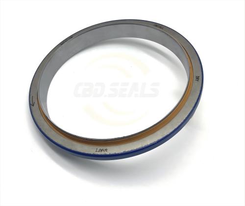
This listing is directly relevant when the diagnosed application is a Caterpillar crankshaft sealing position and the existing part identification corresponds to 4W0452 / 4W-0452.
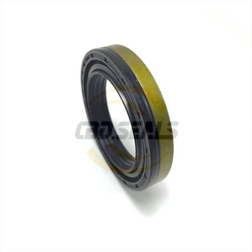
This product is a relevant catalog path when the failure is at the corresponding Caterpillar drive-shaft sealing location and the existing part number and machine application match the listing.
For other applications, review the broader CBD SEALS product shop only after the failure mechanism and basic application data are clear. The purchasing objective is not to find a seal that looks similar; it is to avoid putting the next seal into the same unresolved failure environment.
Oil seal failure troubleshooting FAQ
Why does a new oil seal start leaking quickly?
An early repeat leak often means the original condition was not removed. Inspect installation damage, shaft runout, the shaft surface, wear grooves, shaft lead, misalignment, housing condition, contamination and lubrication before installing another replacement.
Can surface finish cause oil seal leakage?
Yes. Roughness can accelerate lip wear, while directional machining marks or shaft lead can affect lubricant movement at the contact zone. Scratches, corrosion, repair transitions and old wear grooves can also create a leakage path even when the shaft appears generally smooth.
Should the shaft be inspected before replacing an oil seal?
Yes, especially after repeated leakage. Preserve the removed seal, inspect the running track, check for a wear groove and directional marks, and measure runout and alignment as appropriate. Change seal design or material only after the likely mechanical cause has been addressed.
Move from repeated leakage to a documented failure assessment
Bring the failed seal, shaft and housing observations, measured geometry, part identification and verified operating conditions into the next selection discussion. That creates a clearer path from root-cause diagnosis to the appropriate oil seal and rotary shaft seal range without using the next seal as another trial part.