
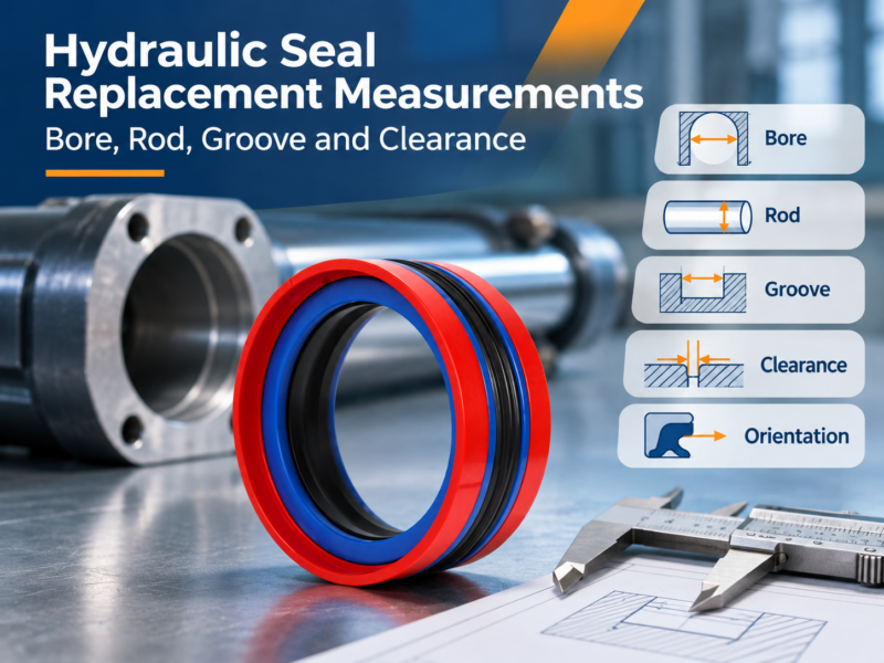
Before replacing a hydraulic cylinder seal, record the cylinder bore diameter, piston rod diameter, seal groove dimensions, mating clearance and orientation of the removed seal. These measurements describe the physical space a replacement must fit, rather than the shape a worn seal happens to retain after removal.
A reliable set of hydraulic cylinder seal replacement measurements identifies where each reading came from, whether the measured component is worn and which details remain uncertain. The old seal is useful evidence, but it cannot establish a replacement size by itself.
Use actual bore, rod and groove readings alongside available drawing dimensions. Keep mating clearance, pressure-facing orientation and photographs attached to that record. When a nominal dimension cannot be established, label it as unknown rather than estimating it from a damaged part.
Which Measurements Identify a Hydraulic Seal Replacement?
The first question is which surfaces the seal actually fits and contacts. A rod seal operates around the moving rod, while a piston seal works between the piston assembly and the cylinder bore. Their groove locations and mating surfaces are different, even when both belong to the same cylinder.
Four groups of measurements establish the main dimensional envelope. The removed seal’s position and orientation provide a fifth, equally important, set of evidence.
Identify the internal diameter and where the relevant readings were taken.
Record the contact-surface diameter and visible dimensional wear.
Identify root diameter, axial width and the component containing the groove.
Describe the gap, the two mating surfaces and the measurement condition.
Label every measurement by its component and reference surfaces; a value recorded only as “groove diameter” or “clearance” is not specific enough to support a reliable comparison.
The aim is not to choose a seal profile at this stage. It is to give the reviewer enough evidence to determine which dimensions are confirmed and which are still needed before a replacement can be assessed.
Separate Housing Dimensions from Old-Seal Measurements
A removed seal can show its former arrangement, approximate profile and visible markings. What it may not preserve is its original manufactured size. Compression, wear, swelling, temperature exposure or removal damage can leave the seal flattened, stretched or distorted.
That distinction becomes important when a worn part seems close to a standard catalog dimension. The difference may be evidence of service damage rather than proof of another intended size.
Hardware dimensions
Record the bore, rod, piston or gland surfaces and accessible groove geometry. Compare actual readings against approved nominal dimensions and tolerances when a reliable drawing is available.
Removed-seal evidence
Record approximate size, profile appearance, markings, permanent deformation, damage and installed orientation. State clearly that these observations came from a used component.
The housing provides the stronger dimensional reference only when its condition is understood. If a rod or groove has worn beyond its original dimensions, the current reading and the nominal drawing value should both be retained rather than silently substituted for each other.
With the mounting geometry established, hydraulic and pneumatic sealing solutions can be considered against the actual assembly requirements rather than a size inferred from a damaged seal.
Two seals may look similar while requiring different groove geometry, support arrangements or installed dimensions. Compare the hardware measurements and installation configuration before treating either part as a match.
Record Bore, Rod and Groove Dimensions Consistently
A useful dimensional record allows another engineer to understand exactly what was measured without inspecting the cylinder again. That means preserving the measurement location, surface condition, drawing reference and units alongside the number.
For the cylinder bore, identify the internal sealing surface and keep individual readings when measurements vary by position. For the piston rod, identify the contact region and note visibly worn areas. A worn rod diameter is an observed condition, not automatically the nominal specification.
Seal groove dimensions must name the component that contains the groove. A rod-seal housing and a piston groove use different reference surfaces; an unlabeled groove diameter could therefore describe the wrong feature. Relevant corner geometry and neighboring surfaces may also need documentation when they affect the proposed fit.
The measuring method matters as much as the dimension itself. Use an inside micrometer or a dial bore gauge for the cylinder bore, and a micrometer for the piston rod where access allows. Take bore readings at several axial positions and in two perpendicular directions to identify taper or out-of-round conditions. Measure the rod at several points along the sealing travel and in two perpendicular directions as well. Record worn or scored areas separately; do not use a damaged reading by itself to infer the nominal diameter.
For the groove, measure the root diameter and axial width with tools suited to the feature: an internal measuring tool for a rod-seal groove in the gland, and an external micrometer for a piston-seal groove on the piston. Inspect the groove edges, lead-in chamfer and corner radii for burrs or damage that could affect installation. Keep individual readings rather than averaging away differences that may indicate taper, out-of-round conditions or local wear.
The reference surfaces differ by seal location. A rod seal is defined by the rod outside diameter and the gland groove’s internal root diameter and width. A piston seal is defined by the cylinder bore inside diameter and the piston groove’s external root diameter and width. These dimensions describe different components and must not be interchanged.
Measurement Datum, Units and Drawing Annotations
Use the drawing’s datum system when one exists. Otherwise, annotate a photograph or sketch to identify the reference faces, the measured component and the location of each reading. Keep units explicit and label any unit conversions instead of presenting them as original drawing values.
The following record is deliberately simple: it separates what should be measured from what explains the reading.

KDAS Piston Seals
CBD SEALS lists KDAS as a combination piston-seal assembly with sealing and supporting elements. It illustrates why the surrounding piston groove, bore and clearance need to be documented together.
The image is a product reference, not a substitute for measured dimensions or confirmation that the existing cylinder uses this arrangement.
Record actual readings and nominal drawing dimensions separately. Do not treat a field observation as an approved tolerance or a calculated value as a direct measurement.
If readings disagree, preserve the separate values and locations. A reading taken from a damaged surface or with restricted access should be marked provisional, without adding unsupported decimal precision.
Capture Mating Clearance and Old-Part Orientation
Bore, rod and groove dimensions describe the main geometry, but they do not fully define the space around an installed seal. Clearance must be tied to the surfaces that create the gap. For a piston seal, record the piston-to-bore gap; for a rod seal, record the rod-to-gland gap. State whether the value is radial or diametral and whether it comes from an engineering drawing or a measurement of the current assembly.
For concentric components, diametral clearance is the difference between the mating diameters, while radial clearance is the one-sided gap. If eccentricity, side loading or worn guide elements are present, record that condition separately because the local gap may not be uniform.
Where extrusion risk is being assessed, identify the clearance on the low-pressure side of the seal under the relevant operating condition. A drawing may specify a nominal gap, while wear or misalignment can change the actual clearance in service. Keep nominal and observed values separate and compare them with the applicable seal manufacturer’s recommendations. Allowable clearance depends on the seal profile, material, pressure and operating temperature, so do not assume a universal limit.
Identify which gap was recorded
Extrusion clearance is the gap between the moving and stationary components on the low-pressure side of the seal, where pressurized seal material could be forced into the clearance. Its significance depends on the seal profile, material, pressure, temperature and support provided by the assembly.
Compare the measured or specified clearance with the seal manufacturer’s guidance for the actual operating conditions. If the cylinder can move off-center, include guide condition and side loading in the review rather than relying on a concentric nominal value alone.
Record how the old seal was installed
Orientation is especially important for an asymmetric seal profile or an arrangement with adjacent support elements. A close-up of the removed seal may show its shape but usually cannot prove which side faced the pressure chamber.
Photographs taken in relation to identifiable cylinder components give stronger evidence. If pressure-facing direction or component order is no longer known, mark it as unknown rather than reconstructing it from memory.
Once the dimensions and installation arrangement are documented, the next step is to assess whether the seal profile suits the cylinder’s operating conditions. For double-acting applications, see our guide to selecting piston seals for double-acting hydraulic cylinders.
Resolve Missing Dimensions Before Requesting a Match
Incomplete records are common when the cylinder drawing is unavailable, old markings have worn away or the existing hardware shows significant damage. The useful next step is to identify which gaps in the evidence prevent a dependable dimensional comparison.
If a critical bore, rod or groove dimension remains unknown, the removed seal alone cannot settle it. Photograph visibly worn regions, retain actual readings and note what further verification would be needed. Do not round an uncertain value to the nearest familiar catalog size.
Photographs should complement, not replace, dimension labels. An overall view identifies the component; closer views should show groove location, measurement reference, original orientation and any damage that affects the reading.
A reviewer can work with clearly marked unknowns. Unlabeled guesses create a false impression of certainty and can lead to a replacement that fits the damaged measurement rather than the intended assembly.
Frequently Asked Questions
Can the old seal alone provide the replacement size?
Not reliably. Wear, compression, swelling and removal damage can change a used seal’s dimensions. Treat its profile and measurements as supporting observations; verify the proposed size against the cylinder hardware and available drawings.
Should worn rod dimensions be treated as nominal?
No. A worn rod diameter describes its current condition, not necessarily its original design. Record where it was measured and compare it with an approved drawing or another dependable reference before establishing the nominal size.
What if no drawing is available?
Document accessible hardware dimensions, clear reference surfaces, clearance information and original seal orientation. Add annotated photographs and any verifiable markings. Leave unsupported nominal values unresolved until they can be checked.
How should measurement uncertainty be recorded?
Retain the actual reading, units, location and reason for uncertainty. Identify wear, restricted access or inconsistent readings, and label the value provisional or requiring verification rather than inventing greater precision.
Send a Dimensional Record for a Replacement Review
A replacement request becomes more useful when it describes the existing cylinder hardware rather than providing only a photograph and an estimated size. The aim of hydraulic cylinder seal replacement measurements is to establish the known geometry, the condition of the components and the remaining uncertainties.
One record, with every dimension tied to its source.
Measurements and photographs should tell the same story, including which details still need verification.
A complete record does not necessarily mean every value is already confirmed. It means each value has a source, and each limitation is visible. This supports a more focused replacement review without confusing worn component dimensions with their original nominal geometry.
Dimensional agreement is essential but does not independently establish suitability for all operating conditions. Once the measurements are organized, the broader seal requirements can be considered through the appropriate fluid power solution.
Send the cylinder bore, piston rod, groove and clearance measurements, together with any available drawing references. Include the equipment details and identify dimensions that still require verification. If photographs or technical drawings are available, mention them in your message so the team can advise how to share the files.