
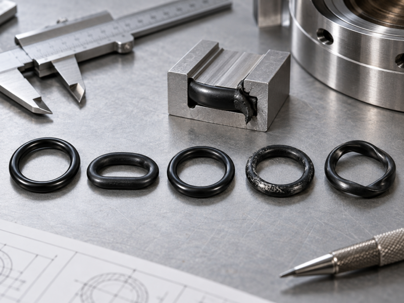
Effective O-ring failure diagnosis starts before another seal is installed. A leak confirms that the sealing system has lost performance, but it does not tell the maintenance team whether the initiating problem is the O-ring, the groove, clearance, mating surface, lubrication, installation or operating conditions.
Before replacing the failed part with another O-ring of the same size, record where the leak appeared, when it began, whether the seal was static or moving, and what was happening to pressure and temperature. Then examine the removed seal before it is cleaned, stretched or discarded. Persistent flattening can indicate compression set, ragged edge damage can point toward extrusion, a directional wear track suggests abrasion, and helical cuts suggest spiral failure. The visible damage is evidence, not a complete root-cause conclusion.
Ask when the leak occurs, where the damage sits relative to pressure and motion, and whether the mark is local, circumferential, parallel to motion or angled around the seal. Those three clues usually tell the team what to inspect next.
Use Leakage Timing to Narrow the Investigation
Leakage timing can eliminate possible causes before the damaged O-ring is examined in detail. A seal that leaks during the first pressure test deserves a different diagnostic path from one that ran normally for many cycles and then began leaking only when pressure increased.
Inspect installation cuts, pinching, twisting, contamination, incorrect seating and sharp assembly features.
Look for progressive wear, friction, lubrication loss, nibbling, material change or dynamic instability.
Check the low-pressure side, clearance gaps, pressure cycling, component movement and deflection.
Check elastic recovery, permanent deformation, hardening, softening, swelling and shrinkage.
A failed seal can carry evidence from several events. A small installation nick may later become a larger tear. Chemical softening may make extrusion easier. Misalignment may first produce abrasion and later contribute to twisting. The final appearance should therefore be read as a sequence, not as proof that every mark developed at the same time.
Once the system cause and replacement requirements are understood, the confirmed evidence can be used to narrow suitable O-rings instead of selecting a different material simply because the previous seal failed.
How to Distinguish These Four O-Ring Failure Patterns
Start by noting whether damage is smooth or torn, local or circumferential, aligned with motion or angled across it, and concentrated on the pressure side or low-pressure side. The schematics below are visual screening aids rather than dimensional drawings.
Set
O-Ring Compression Set
Loss of elastic recovery leaves the cross-section visibly flattened rather than returning toward its previous shape.
Nibbling
O-Ring Extrusion Failure
Material is forced toward a gap and progressively damaged, often producing the appearance commonly called nibbling.
Wear
O-Ring Abrasion
Progressive surface loss that follows movement is more consistent with frictional wear than with one localized installation cut.
Failure
O-Ring Spiral Failure
Uneven sliding can make sections of a dynamic O-ring roll and twist, producing diagonal or spiral damage around the circumference.
Two failed seals can look similar while having different initiating causes. Always combine the visible pattern with leakage timing, seal orientation and the operating state in which the leak became worse.
What Each Failure Pattern Should Make You Check Next
Compression Set: Confirm Permanent Deformation
O-ring compression set is not simply the fact that an O-ring becomes flat while installed. Compression is part of normal sealing. The diagnostic concern is whether the cross-section remains permanently deformed and has lost enough recovery to maintain contact as the joint or operating condition changes.
When investigating why O-rings flatten, compare the removed seal with an unused reference where practical. Review actual operating temperature, not only the nominal process value, and look for simultaneous hardening, softening, swelling or other evidence that the material condition also changed.
Extrusion: Follow the Nibbling Back to the Gap
O-ring extrusion failure occurs when elastomer is forced into a clearance gap and damaged at the edge of that gap. The strongest signs of O-ring extrusion are usually ragged, chipped or feathered material concentrated where pressure pushes the seal toward available clearance.
Pressure alone is not a complete explanation. Component movement, eccentricity, changing clearance, pressure cycling, edge condition, swelling or softening may all change the effective extrusion risk. Inspect the hardware under the most relevant operating condition available rather than assuming a depressurized gap represents the loaded system.
Abrasion: Use the Wear Direction as Evidence
O-ring abrasion normally develops through repeated relative motion. A broad polished band, directional scratches, roughened rubber or progressive surface loss is more consistent with wear than a single sharp installation nick.
The direction of abrasion marks on O-rings helps locate damaging contact. A track parallel to rod or piston movement points toward the dynamic interface, but the underlying problem could still be contamination, a rough mating surface, lubrication loss, side loading or alignment error. Follow the wear track back to the mechanical condition.
Spiral Failure: Look for Rolling and Twisting
Spiral failure in dynamic O-ring seals produces angled or helical marks rather than a simple motion-parallel wear band. The pattern can develop when one section slides while another rolls, progressively twisting the O-ring during reciprocating movement.
The seal should not be the only component inspected. Check whether the moving hardware remains concentric, whether side load changes through the stroke, whether lubrication is distributed consistently and whether the O-ring may have been rolled or twisted during assembly. For reciprocating applications, also review stroke speed, stroke length, pressure direction, installed squeeze and groove geometry because these conditions can influence whether sections of the ring slide, roll or twist.
Do Not Confuse Installation Damage or Chemical Change With Service Wear
Two conditions commonly complicate how to diagnose O-ring failure. Installation damage may resemble abrasion or tearing, while chemical change can alter seal dimensions and mechanical behavior before the final mechanical damage becomes obvious.
Installation Cuts, Shaving and Pinching
Installation damage tends to be localized. A clean nick, slice, shaved section or pinch mark deserves attention when the seal leaks immediately after assembly.
Inspect every feature the O-ring passed during installation, including threads, ports, groove edges, sharp shoulders and tool-contact areas. Repeated damage at the same location strongly suggests an assembly-path problem.
Swelling, Shrinkage or Material Change
Fluid exposure can change an O-ring before obvious mechanical damage develops. Swelling may increase friction or reduce available clearance, while shrinkage may reduce sealing contact.
Record process media, cleaning fluids and lubricants. Do not identify chemical incompatibility from appearance alone when the actual material identity or exposure history is uncertain.
Chemical softening can precede nibbling. A small installation cut can later become a larger tear. Misalignment can create abrasion before a spiral pattern appears. Root-cause analysis should explain how the full damage pattern developed over time.
O-Ring Failure Diagnosis Matrix
Use the visible evidence to prioritize the next inspection rather than to declare a root cause immediately. The matrix is deliberately cautious because the same final appearance can have more than one upstream cause.
Trace the Root Cause Back to the Groove, Surface, Material and Operating Conditions
Most O-ring failure modes make more sense when the failed seal is treated as one component in a sealing system. Once the damage pattern has narrowed the investigation, sort the possible causes into conditions that can actually be inspected and corrected.
- Groove and clearance
- Inspect gland condition, edge geometry, available clearance and whether the effective gap changes under pressure, load or component movement.
- Mating surface
- Look for scratches, rough areas, local damage and inconsistent contact across the full dynamic travel path.
- Lubrication
- Check whether lubrication is present, suitable for the system and distributed consistently rather than displaced from one part of the stroke.
- Material condition
- Note hardening, softening, permanent deformation, swelling or shrinkage before deciding that a new material or hardness is required.
- Installation
- Review cuts, pinching, contamination and twist introduced before operation. Repeated damage at one assembly feature deserves process correction.
- Operating conditions
- Review pressure cycling, thermal change, vibration, side loading and motion that may not be obvious during a stationary shutdown inspection.
Preserve the Failed Seal Before Installing the Replacement
The removed O-ring is physical evidence. Aggressive cleaning, unnecessary stretching or disposal can remove information that would otherwise help distinguish permanent deformation, wear, extrusion and installation damage.
Preserve what the system is telling you.
Clear photographs help, but the actual seal and its installed orientation make repeated failures much easier to compare.
Verify the Cause Before Changing the O-Ring Specification
The objective of O-ring failure diagnosis is not merely to give the damage a name. It is to identify which variable should be checked before another seal returns to service.
Compression set should lead to a review of elastic recovery, heat exposure and installed compression. Extrusion should lead to pressure, clearance and hardware movement. Abrasion should lead to the dynamic interface, contamination, lubrication and alignment. Spiral failure should lead to twisting, rolling and the way the hardware guides the seal through its stroke.
If material, hardness, groove, surface and lubrication are all changed at once, a later successful run may not reveal which change corrected the problem. Where maintenance constraints allow, use the failure evidence to identify the highest-priority cause and document each corrective action.
When a Material Review Is Actually Justified
A different material should enter the discussion only after the failure evidence points toward fluid exposure, temperature, ageing or another material-related condition. It should not be used to hide an unresolved groove, surface or installation problem.

CR (Neoprene) O-rings
CR (Neoprene) can be considered when the failure investigation points to a material or service-media issue. Check the actual operating conditions first, then compare the compound with the required temperature, pressure, size, hardness and sealing duty.
Keep the failed part and field record, verify the system cause, and then decide whether the replacement needs a different material, hardness, groove condition or operating approach. Product-family comparison should come after those requirements are defined.
If the cause is understood, compare available seal options against the confirmed size, material and service conditions. For repeated or unclear failures, send the failed-seal photos together with leakage timing, motion, pressure, temperature, media, O-ring ID and cross-section or dash size, and material or hardness if known. If the material or hardness is unknown, state that rather than guessing.
Frequently Asked Questions
What does compression set look like on an O-ring?
What causes O-ring extrusion or nibbling?
How can abrasion be separated from installation damage?
What causes spiral failure in a dynamic O-ring?
Should a failed O-ring be replaced with a harder compound?
Can one failed O-ring show more than one failure pattern?
Preserve the O-ring, record the operating conditions and verify the root cause before changing the replacement specification. The corrective action may belong in the groove, clearance, surface, lubrication, installation process, operating condition or material—not necessarily in the O-ring alone.