
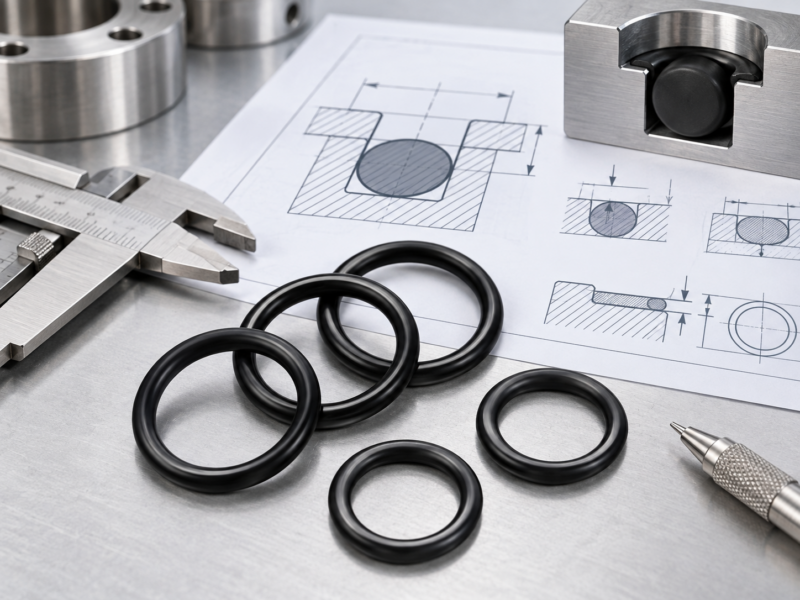
O-Ring Groove Design Checklist: Squeeze, Stretch, Gland Fill and Extrusion Gap
An O-ring groove should not be approved simply because the nominal squeeze looks acceptable. Squeeze is only one part of the installed geometry. Stretch can change the effective cross-section, gland fill determines whether displaced or expanded elastomer has enough room, and the extrusion gap determines how much unsupported clearance the seal may see under pressure.
A useful O-ring groove design checklist treats groove depth, groove width, cross-section, squeeze, stretch, gland fill, clearance and manufacturing tolerances as one connected system. The practical sequence is to identify the seal arrangement first, calculate each condition at its relevant limits, and then confirm that changing one variable has not pushed another outside the intended design envelope.
Release it when minimum and maximum squeeze, installed stretch, maximum gland fill and maximum extrusion clearance remain mutually compatible after tolerances, temperature effects and expected component movement are considered.
Classify the Seal Before Checking Groove Dimensions
The first design question is not groove width or squeeze percentage. It is what type of seal the groove must support. Static and dynamic applications impose different requirements, and radial and axial arrangements create compression in different directions.
A static seal mainly needs to maintain contact as pressure, temperature and material condition change. A dynamic seal must maintain that contact while a component moves, so friction, wear, ring stability and changing clearance become part of the geometry review. Likewise, a radial seal is compressed between radial surfaces such as a piston and bore or a rod and housing, while an axial seal is compressed between opposing faces.
Static radial
Establish the sealing diameter, groove diameter, effective radial gland depth and pressure-side clearance. Minimum squeeze and maximum extrusion gap often become separate tolerance-stack questions.
Static axial
Establish groove depth, groove width, opposing face position and pressure direction. Ring location matters because pressure can move the seal toward one side of the gland.
Dynamic radial
Add motion, friction, wear and changing component position to the radial checks. A groove that appears workable while stationary may behave differently through a reciprocating cycle.
Dynamic axial
Review face compression together with relative movement. The design has to maintain sealing contact without creating an unnecessarily restrictive or unstable moving interface.
Once the sealing arrangement is clear, the available O-rings can be reviewed against the size and service requirements. That selection step should follow the geometry check rather than using material hardness to compensate for an unresolved gland.
Connect Squeeze, Stretch, Gland Fill and Extrusion Gap Before Release
The most common design error is to calculate these variables as independent checks. Groove depth affects squeeze. Installation stretch can change the cross-section used in that squeeze calculation. Squeeze and groove width influence gland fill. The mating hardware then determines the unsupported extrusion clearance. A design change should therefore trigger the calculations it affects downstream rather than being treated as a local dimension edit.
Establish the Cross-Section and Effective Gland Geometry
Start with the O-ring cross-section and every hardware dimension that establishes the installed cavity. Depending on the arrangement, that may include groove depth, groove width, groove diameter, bore or shaft diameter, face spacing and the clearance between mating components.
Keep nominal values and tolerance limits separate. A nominal CAD section may look generous while the largest permitted O-ring cross-section and smallest permitted gland create a much more crowded condition. At the other end of the stack, a small cross-section combined with a deeper gland can reduce sealing contact.
For radial seals, distinguish the machined groove depth from the effective installed gland depth. Final compression is created by the assembled hardware, not by the groove feature in isolation. If the design uses an AS-568 size, the AS-568 O-ring size chart provides a dimensional reference before those dimensions are placed into the gland calculation.
Calculate O-Ring Squeeze at Both Ends of the Tolerance Stack
O-ring squeeze is the reduction in seal cross-section created by the assembled gland. A simplified representation is:
The exact dimensional inputs depend on whether the seal is radial or axial, but the engineering question is the same: what are the minimum and maximum squeeze conditions after the relevant tolerances are combined?
Minimum squeeze identifies the geometry with the least compression. Maximum squeeze identifies the opposite condition, where the ring occupies more of the available gland depth. In a dynamic application, the high-squeeze end can also change friction, heat generation and wear behaviour, so a static groove assumption should not simply be carried into a moving seal.
An O-ring squeeze calculation should therefore be based on installed geometry rather than a nominal cross-section divided by a nominal groove depth. Acceptance limits should follow the applicable seal standard, manufacturer guidance and service requirements rather than a universal percentage applied to every application.
Check Installation Stretch Before Accepting the Squeeze Result
O-ring stretch is not merely an assembly concern. For applications where the O-ring is expanded over an installation diameter (such as many piston/external sealing arrangements), expanding the ring changes its installed geometry and can reduce its effective cross-section. A squeeze calculation based only on the free cross-section may therefore overstate how much compression exists after installation.
The useful question is not whether one universal stretch percentage is acceptable. Acceptable O-ring stretch factors depend on size, installation geometry, static or dynamic duty and the dimensional guidance being used for the selected ring.
Calculate the required installation stretch, determine the installed cross-section through the appropriate engineering method, and then return to the squeeze calculation. If the updated cross-section materially changes the squeeze envelope, reconsider the O-ring size or gland rather than continuing with the original nominal result.
Perform the O-Ring Gland Fill Check at Maximum Seal Volume
Squeezing an elastomer changes its shape; it does not make the material disappear. Material displaced by compression needs somewhere to move within the groove. This is why groove width should not be selected independently from groove depth.
The useful O-ring gland fill check evaluates the condition that produces the highest fill rather than nominal volume divided by nominal cavity volume. That means comparing the largest relevant installed seal volume with the smallest available gland volume, then considering verified operating effects that may increase seal volume or reduce cavity space.
This is also why squeeze and gland fill must be checked together. Making a groove shallower may increase squeeze, but the same change reduces cavity volume. Narrowing the groove can have a similar effect on fill even though the squeeze calculation itself may not change.
Determine the Maximum O-Ring Extrusion Gap in Service
The O-ring extrusion gap is the unsupported clearance into which elastomer can be driven when differential pressure loads the seal toward the low-pressure side. The critical value is the maximum physical gap that can occur in operation, not simply the nominal machining clearance.
Include tolerances that enlarge the gap, plus eccentricity, component movement, bearing clearance, assembly position, deflection and relevant thermal dimensional changes. In a dynamic assembly, check whether the gap varies over the stroke or operating cycle.
A harder compound can change extrusion resistance, but increasing hardness does not remove an oversized or unstable hardware gap. During O-ring extrusion gap troubleshooting, determine first whether the surrounding hardware provides adequate support. If a backup ring becomes part of the solution, include it in the groove-width and gland-volume calculations instead of adding it after the gland has already been finalized. The CBD SEALS back-up ring size charts provide a useful dimensional reference when that configuration is being considered.
Change groove depth and both squeeze and gland fill should be revisited. Change O-ring size and installation stretch may change as well. Add a backup ring and the available gland width and volume change. The design loop ends only when the complete set of variables remains compatible.
Temperature, Material Expansion and Tolerances Change the Boundary Conditions
A groove can pass every nominal calculation and still be weak at one corner of the production or operating envelope. Manufacturing variation changes the cavity. Temperature changes both the elastomer and the hardware. Media exposure can change elastomer volume. Dynamic components can shift position or deflect under load.
Nominal geometry is the center of the study, not the release criterion.
CAD
Minimum squeeze state
Combine the dimensions that produce the least compression, including installed cross-section effects where applicable.
Maximum squeeze and fill state
Combine the largest relevant seal section or volume with the smallest available gland condition.
Maximum extrusion-gap state
Combine the hardware conditions that create the largest unsupported clearance on the pressure-loaded side.
Temperature can change both sides of the sealing interface
Do not assume that only the O-ring changes dimension with temperature. The shaft, piston, bore, housing and groove also respond to temperature according to their materials and dimensions. Differential movement can alter both squeeze and extrusion clearance. The correct thermal correction therefore needs verified material data for the actual design rather than a generic fixed allowance.
Material volume change affects gland fill directly
If exposure to the operating medium increases elastomer volume, gland fill rises even though the machined groove has not changed. Another operating condition may reduce contact or change elastic behaviour. Material compatibility and gland geometry are separate engineering questions, but they interact through the installed volume.
Do not force every risk into one “worst-case” stack
The dimensions that create minimum squeeze may not be the dimensions that create maximum gland fill, and neither combination may create the largest extrusion gap. Build each limit state around the physical result being checked. If two dimensions are functionally related, avoid combining extremes that cannot occur together in the real assembly.
When the design operates near a dimensional boundary or under severe pressure, temperature or motion conditions, confirm the final groove calculations against applicable engineering data or supplier guidance before the drawing is released.
Use the Failure Symptom to Decide Which Geometry to Recalculate First
A failed or inconsistent seal does not automatically identify one root cause. The symptom should instead narrow the first part of the geometry to recalculate. Installation condition, material compatibility, surface condition and operating history may still need separate investigation.
Four Groove Design Mistakes That Commonly Hide in Clean Drawings
Designing from nominal dimensions only
Nominal geometry is useful for layout, but it does not reveal minimum sealing contact, maximum gland crowding or maximum clearance. Each of those states needs its own dimensional combination.
Checking squeeze without the full stack
A geometry change that raises squeeze can also increase gland fill. Another tolerance combination can reduce squeeze while enlarging the extrusion gap.
Using higher hardness to hide excessive clearance
Hardness can influence extrusion resistance, but it does not correct uncontrolled clearance, eccentricity, component movement or deflection. Stabilize the hardware boundary first.
Applying static groove logic to a dynamic seal
Movement adds friction, wear and positional stability to the problem. A gland that maintains static contact is not automatically suitable for a reciprocating or rotating interface.
Drawing-Release O-Ring Groove Design Checklist
A checked item should mean that the condition has been evaluated at the relevant limit, not simply that a nominal value exists on the drawing.
Seal arrangement
Cross-section and gland
Squeeze, stretch and fill
Clearance and operating limits
Finish the operating and groove boundary review before finalizing material and hardness.
For an OEM or maintenance handoff, provide the seal arrangement, groove dimensions, tolerance limits, pressure, temperature, medium, movement and any known failure symptom. That creates a useful engineering basis for selecting material and hardness instead of asking the compound to compensate for an unresolved groove.
Compare Material Options Only After the Groove Envelope Is Defined
Groove geometry and material selection solve different parts of the sealing problem. Once the gland envelope is controlled, the operating medium, temperature, pressure, motion and other service requirements can be used to narrow the material family. The following CBD SEALS product pages are relevant examples of material-specific O-ring options; they should not be selected from groove geometry alone.

Relevant when chemical, oil and elevated-temperature resistance are part of the application requirements. Confirm the exact medium, temperature, pressure, size and static or dynamic duty before selection; the material choice should follow the completed groove and tolerance review.

Relevant where weathering, oil or selected chemical exposure forms part of the service environment. Confirm the actual medium and operating limits together with pressure, motion and the approved groove size before treating this as a candidate material.
Move From Groove Approval to O-Ring Selection
Once squeeze, stretch, gland fill and extrusion clearance have been checked through the relevant tolerance envelope, compare the available O-ring options against the actual medium, temperature, pressure, motion and dimensional requirements. For critical dimensions or uncertain limit conditions, send the available drawing and service data for review.
O-Ring Groove Design FAQs
What should be checked first in O-ring groove design?
Start by identifying the seal as static or dynamic and radial or axial. That determines which dimensions create squeeze, where pressure loads the ring and which hardware clearance becomes relevant to extrusion. Establish the complete installed gland geometry before accepting any squeeze result.
Why must squeeze and gland fill be checked together?
Squeeze changes the O-ring shape and displaces elastomer within the gland. A shallower groove can increase squeeze while simultaneously reducing available gland volume. Groove depth, groove width, installed cross-section and seal volume therefore have to be reviewed as connected variables.
How does extrusion gap affect O-ring selection?
The extrusion gap determines how much unsupported clearance is available when differential pressure pushes the seal toward the low-pressure side. Evaluate the maximum in-service gap together with pressure, component movement, material behaviour and any backup-ring strategy before approving the final configuration.
Can a harder O-ring fix an oversized clearance?
Hardness can influence extrusion resistance, but it does not correct excessive hardware clearance, eccentricity, component deflection or changing position. Establish and control the actual extrusion gap first, then evaluate material and hardness against the resulting geometry and service conditions.
How do tolerances change groove design?
Different tolerance combinations create different design limits. One combination can produce minimum squeeze, another maximum gland fill, and another the largest extrusion gap. A release review should calculate these limit states separately instead of relying on the nominal CAD section.
Release the Groove With Confidence
The purpose of an O-ring groove design checklist is to confirm that the installed seal remains within a workable geometric envelope after manufacturing variation, assembly conditions, pressure, temperature and movement are considered.
Once the groove geometry is validated, material and hardness selection can focus on the actual operating environment instead of compensating for an unresolved design issue.